Le
Net du Kermeur
Solar panel interface
 |
|
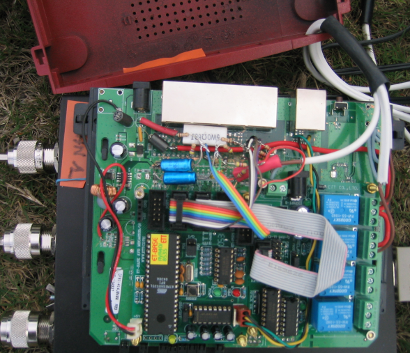
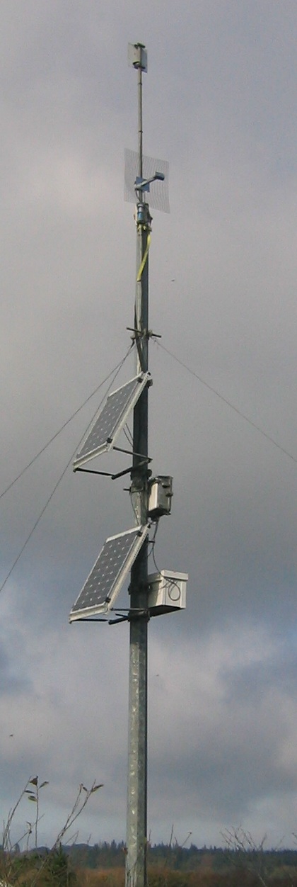
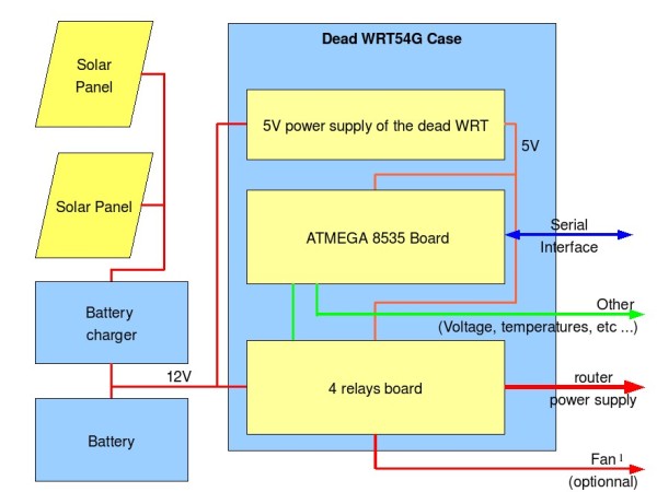
This interface allows to control remotely the solar panel system powering the wireless backbone. The interface provide several measures, and can do some drive too (like starting fans ...). It talks with one of the wireless backbone router.
This article was first posted on the this page on the "Net du Kermeur" website
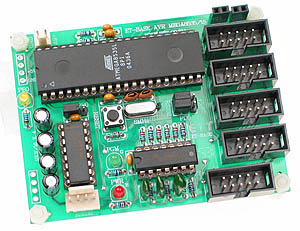
Board with an ATMEGA8535 and a 4 relays board (both bought from Futurlec).
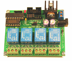
Power used on 5V : ~100mA + 30mA per activated relay; 220mA maximum
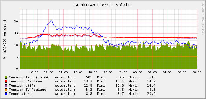
8 measures points, 4 used for internal use : input power supply, usage supply, 5V powering the logical circuit, temperature measure.
The power usage can be calculated by : ( input power supply - usage supply ) / value of the shunt.
8 Input/Output with 4 used for the relays board.
The 4 relays are used for : 2 for the unballasting of power use, 1 fan driving (when the temperature is too hot), 1 free
The internal clock can be used for command duration or waiting; it will allow to run some stuff at a given time in the next version of the software. The precision isn't very high, the clock need to be re-sync quite often (cf DATE command).
The external interface is a serial connexion : 19200 bauds 8N1, connected to the wireless router (Mikrotik RB433)
Program sources for Atmega8535 (GCC/AVR).
The invite looks like this: "-->". This show the interface is ready to receive a new command. If it doesn't show at the terminal launch, simply enter a cariage return to force the banner display. Commands are case insensitive.
If everything is ok, the command will return a OK, else it return an ERR.
HELP
Due to memory issues, the help isn't integrated anymore, but return this page URL.
VERSION
Return the version of the ATMEGA8535 software (now AVR004 version 0.01).
DEBUG
Switch to the verbose ouput mode
DATE [OFFSET]
Return the date
The system's date must be set before, or it's return the uptime.
Setting the date is done with the DATE nnnnn, where nnnnn is the time in seconds since 01/01/1970 (epoc).
UPTIME
Return the system uptime.
TESTLED
Use the pin 1 of the port B to blink a led with a rate of 1 beat by second. When serial connexion occurs, the blinking speed change.
The LED/PBO jumper need to be on LED position.
This provide a way to check the program is still running and the serial transfert, but of course use a IO.
re-run the command to stop the test.
PORTB 1..8 [ON-OFF [DUREE]]
Toggle the state of the PORTB 1-8 output.
Warning: The OFF state is used for the 0V ouput (active state), ON 5V.
PORTBS
Show the state of PORTB ouputs 1-8.
MODEB [nn]
Show or modify the mode of the port 1-4. By default, they are used in input mode, set to 1 to force in output mode.
RELAIS 1..4 [ON-OFF [DUREE]]
This is for the commands on PORTB 5-8 ON-OFF [TIME]; this ports are used internaly by the relays board.
The ON state is used for the active state of the relay (!= the PORT command)
ADCA 1..8
Analogue conversion on the PORTA 1-8.
ADCAS
Same a ADCA, but return the list of values for all pins.
WATCH [ nnn Commande | OFF ]
Run a command RELAIS or PORTS if no command was received during nnn seconds, example:
WATCH 600 RELAIS 1 ON 10
Will activate the relay 1 during 10 second if the system doesn't receive valid command during 10 minutes.WATCH OFF
Stop the watchdog.Communication example
----------------------------------------

LNDK_AVR006v0.01 11/2007

----------------------------------------

-> date

Date 2008-05-21 20h 27m 33s

OK

-> uptime

Uptime 118j  6h 53m 02s

OK

-> adcas

ADC 1 : 1

ADC 2 : 0

ADC 3 : 0

ADC 4 : 1

ADC 5 : 533

ADC 6 : 520

ADC 7 : 508

ADC 8 : 291

OK

-> dummy

ERR
Of course you need a serial port and a serial connexion software to talk with the system (RS232)
Here a short list
OS Program Notes Linux, *BSD minicom Automatisation with option --script, example MacOsX ZTerm + serial adaptor on Mac Openwrt microcom (script possible) + package setserial (and MAX232 interface on the WRT54GL) RouterOS /system serial-terminal serial0 (no script) From a RouterOS(winbox, ssh, etc ...) console
Automatisation with Perl Expect moduleTelnet on serveur RFC2217 (cf /port remote...) From a remote host, script Perl Net::Telnet Windows Hyperterminal